


 56 / 60

54
World Cement
North America 2019
loads in the cement-making process,
high‑efficiency backward curved or backward
inclined blade designs became preferred
for their more efficient operation, reduction
of power costs, and, in turn, cost/tonne
of product produced. These BIC and BIF
designs became popular in new installations;
in addition, many existing installations were
retrofitted with these high efficiency designs.
Through testing and actual operation history,
it was discovered that a backward inclined
curved blade, streamlined for laminar flow
across the blade, would reduce the hard,
layered-type of buildup on the top of the blade.
By matching the blade to the streamlines of
the flow, the impact of the material entrained
in the gas stream can be minimised on the top
of the blade, if not eliminated. However, just
by the nature of the shape of the blade, the
concave curvature on the bottom side of the
blade becomes subject to buildup with a soft,
powdery material.
Dangers of buildup
Having material buildup on either side of
the blade is undesirable. During operation,
the buildup on the blades normally occurs
non‑symmetrically, leading to a heavy spot
on the rotor and creating an imbalanced
condition, potentially damaging vibration at
the bearings. In addition, the buildup will
eventually begin to shed unevenly off the
blades; again, creating a heavy spot on the
rotor and leading to vibration. At a defined
setpoint level of vibration, to prevent damage
to the bearings and the shaft journals the fan
is normally shut down and the rotor cleaned.
This downtime is not only inconvenient but is
also extremely costly.
A solution
To address this problem, ProcessBarron has
developed a new system that will minimise, or
even eliminate this buildup of soft material on
the bottom side of a backward curved blade.
This extends the operating time between these
shutdown events, which are required to clean
the preheater ID fan rotor. Using compressed
air with high-energy nozzles, the buildup is
continuously swept off the blade with timed
blasts or puffs of compressed air released
instantaneously by a fast-acting, high-volume
valve (sometimes referred in the industry as
a poppet valve). It is a simple, easy to install,
and cost-effective system. The concept
is similar to the air cannons used to keep
material from bridging and limiting production
rate commonly found on the pre-calciner.
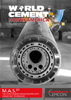
A compressed air system consists of a
cleaning lance, a compressed air reservoir
or accumulator tank, and a fast-acting,
high‑volume valve or poppet valve. The
cleaning lance has a row of nozzles installed
on it that are positioned close to the leading
edge of the rotor blades. On a single-inlet
fan design, one lance is required, whereas
on a double-inlet fan two lances are needed.
The lances are designed to be adjustable so
that the best angle of attack for the pulse of
compressed air can be made relative to the
angle of the backward curved blade. The
Cross-sectional view of fan with compressed air
lances.
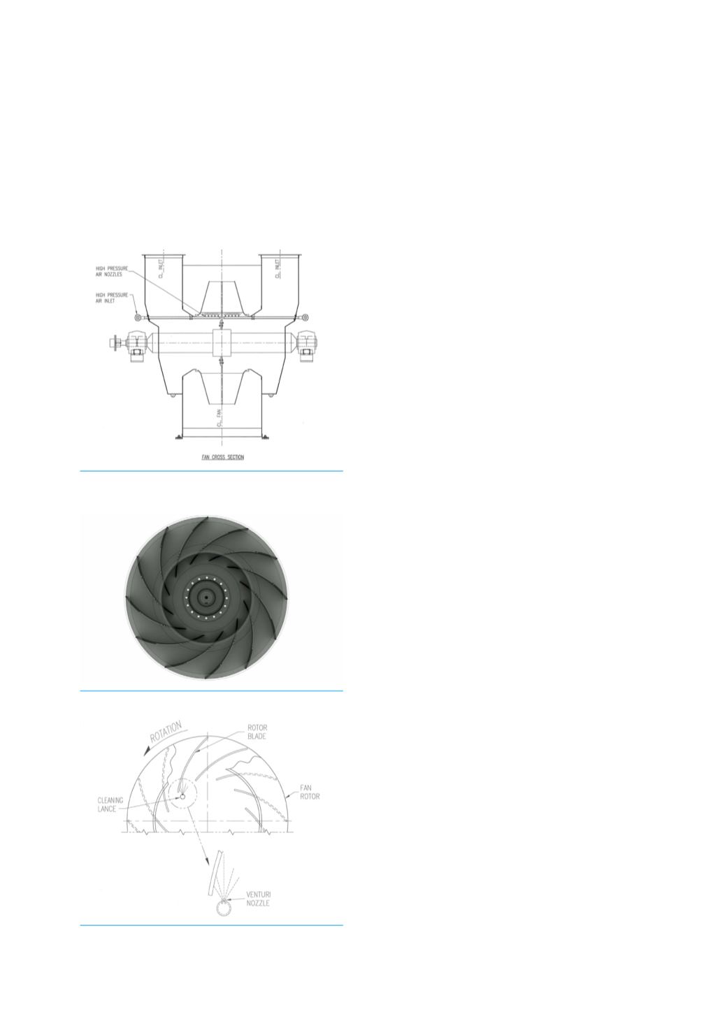
Elevation of backward curved blade design.
Elevation of lance with nozzles and spray
pattern.