


 76 / 84

North America 2018
74 \
World Cement
Tensioning
The ability to maintain the proper force required
to keep the blade edge against the belt is a key
factor in the performance of any cleaning system.
Blade-to-belt pressure must be controlled to achieve
optimal cleaning with a minimal rate of blade wear.
There is a popular misconception that the harder
the cleaner is pressing against the belt, the better
it will clean. Research has shown that there is
actually an optimum range of blade pressure, which
will most effectively remove carryback material.
Increasing tension beyond this range raises blade-to-
belt friction, thus shortening blade life, increasing
belt wear, and increasing power consumption,
without improving cleaning performance.
Too much pressure can prevent proper contact,
forcing the tip away from the belt and leaving a
small gap that can lead to hydroplaning. Material
will wedge between the blade tip and belt,
potentially leading to premature wear of both the
blade and belt.
Operating a belt cleaner below the optimum
pressure range delivers less effective cleaning and
can actually accelerate blade wear. A belt cleaner
barely touching the belt may appear to be working
from a distance; however, excessive amounts of
carryback are being forced between the blade and
the belt at high velocity. This passage of material
between the belt and the blade creates channels of
uneven wear on the face of the cleaner. As material
continues to pass between the blade and the belt,
these channels increase in size, rapidly wearing the
blade to a jagged edge.
Another common source of blade wear that often
goes unnoticed, even with a properly installed and
adjusted cleaner, is the running of an empty belt for
long periods of time. Even though the cargo may be
abrasive, it often has moisture in it that serves as a
lubricant and coolant. Small particles embedded in
the empty belt’s surface can be as much as 60 g/m
2
,
creating a form of sand paper. In effect, running the
belt when empty doubles the wear rate of both the
blade and the belt.
There is a complex geometrical relationship
between the tensioner’s spring force and the blade
geometry during its wear life. Most tensioners are
designed to be a compromise between optimal
pressure at a single point of wear and acceptable
pressure over the entire wear profile. In spring
tensioners (such as twist or coil types), the spring
force decreases as the blade wears. Therefore,
designers are trying to optimise four factors:
the decreasing spring force, the changing blade
geometry, blade width, and blade type.
As urethane cleaner blades wear, the surface
area of the blade touching the belt increases.
This causes a reduction in blade-to-belt pressure
and a corresponding decline in cleaner efficiency.
Therefore, most mechanically-tensioned systems
require periodic adjustment (re-tensioning) to
deliver the consistent pressure needed for effective
carryback removal.
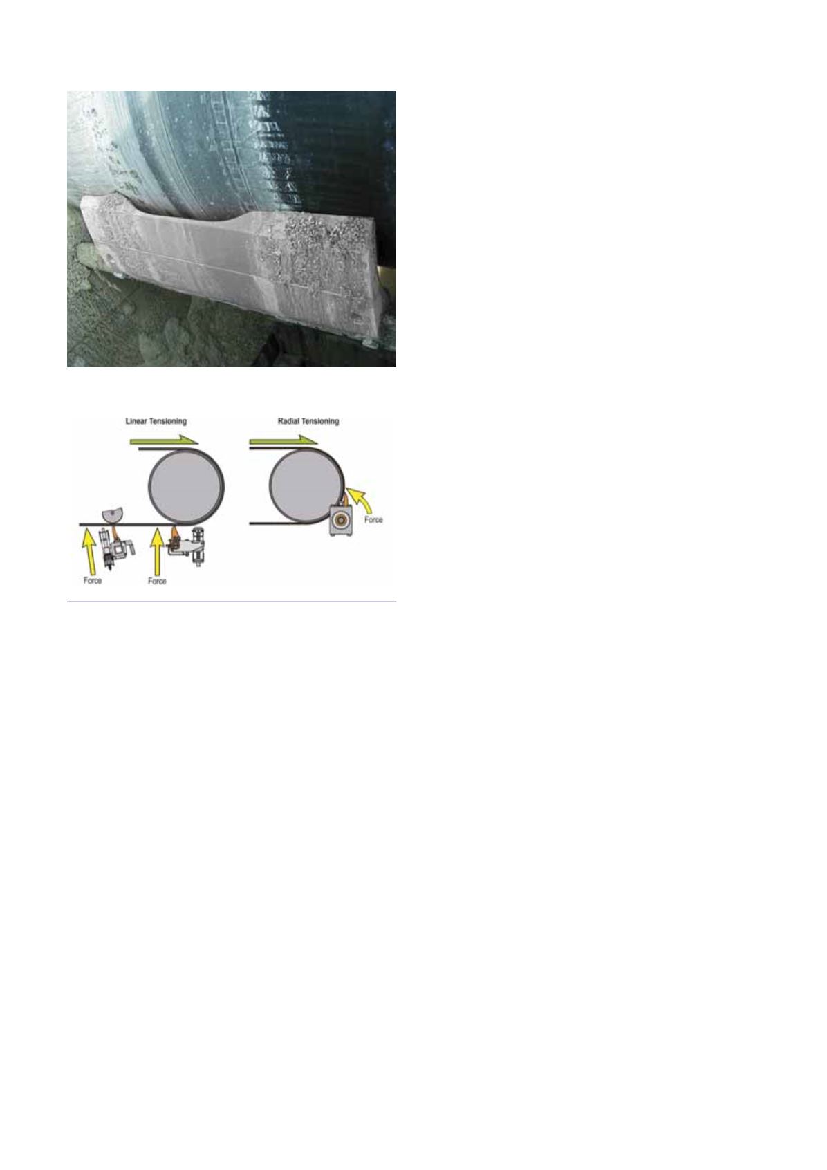
There are competing theories on belt cleaner
tensioning. Linear-tensioned cleaners are pushed up
in a line against the belt, while radially-tensioned
cleaners are installed with a mainframe as an axis
and rotated into position. In addition, some hybrid
systems incorporate vertical tensioning with a radial
relief mechanism (Figure 3).
Linear-adjusted cleaners generally require access
to both sides to provide balanced pressure. Because
of this, the tensioners for these cleaners often have
some form of powered adjustment that can be
remotely controlled. Linear tensioners maintain a
constant cleaning angle as the blade wears and can
usually be designed to allow easy withdrawal of
the cleaner for maintenance, without removing the
tensioner.
Radial-adjusted cleaners have several practical
advantages over linear designs: they are easier to
install and can more readily rotate away from the
belt to absorb the shock inherent in belt motion and
splice passage.
To overcome the problem of the blade angle
changing as the blade wears, a radial-adjusted
Figure 2. As the centre of the blade wears unevenly, the
outer edges create an effect called a ‘smiley face’.
Figure 3. Linear and radial belt tensioning.