


 42 / 60

40
World Cement
North America 2019
Application review
There are many unique applications implemented
in a cement plant. However, the science utilised to
manufacture portland cement has remained largely
unchanged for many years. With that said, many
engineered applications, no matter the age or location
of the cement plant, are largely similar. One can easily
identify slow speed, small to medium horsepower,
and low voltage applications that require head drives.
These include bulk material handling conveyors,
clinker drag conveyors, screw conveyors, and bucket
elevators. These four specific applications can
be found in every cement plant. They encompass
analogous design parameters.
An existing important bucket elevator, operating
at 28 RPM, has an aging gear reducer with the
associated design parameters: 64:1 speed reduction
ratio, foot-mounted, 72.3 kW (97 hp.) mechanical
rating, double reduction offset parallel, and shrink
disc mount to a 150 mm head shaft. A foot‑mounted
Baldor‑Reliance
®
induction motor with #ECP4410T-4,
125 hp. (93 kW), 0.85 power factor, NEMA frame
444T, 4 pole, 3 ph/60 Hz/460 V powers the head
drive. The motor and gear reducer are connected via
a high-speed flexible coupling.
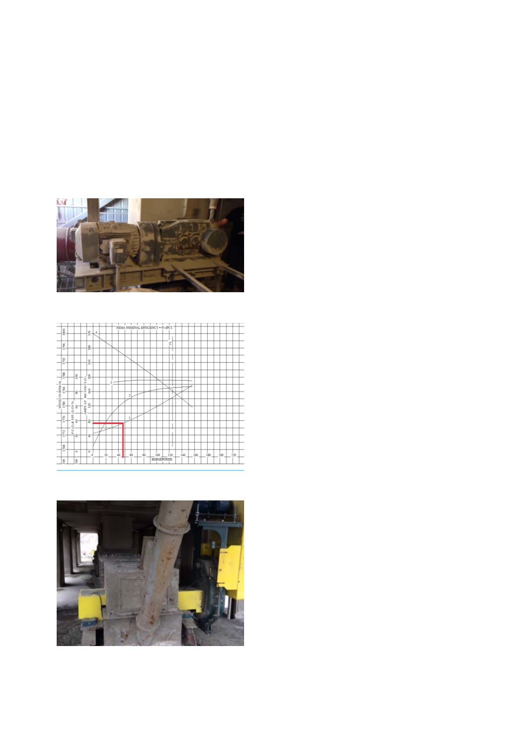
Plant control systems indicate that the motor is
well oversized for the application and operates, on
average, at 50% of full load amperage. By locating the
motor manufacturer’s performance curve (Figure 2),
one can determine that at 50% full load amperage (or
72 amps when FLA = 144 amps), the interpolated
required working horsepower will be approximately
46 hp. (34.3 kW).
The combined powertrain, though well mismatched
by conventional engineering practices, has performed
admirably for the last 20 years, with the exception of
the two-fold gear reducer rebuilds and intermittent
bearing and seal replacements. The reducer, now
obsolete, catastrophically fails, causing an application
outage and lost time production. What should the
cement plant do with no application critical auxiliary
plan in place? With a change of paradigm and reverse
engineering in order to verify form, fit, and functionality,
a timely replacement solution does exist.
Selecting an induction motor
A motor achieves its highest efficiency when
operated at between 75% and 80% below full load
horsepower. Additionally, a motor utilises its peak
power factor when operated at full load or above.
Although it is not uncommon to operate a motor
above its nameplate horsepower, this practice is
not recommended due to the introduction of high
temperature to the motor insulation and bearings.
Consequentially, a reduction in the optimal service life
of the equipment will result.
The original motor design was 125 hp. (93 kW)
and the working horsepower required to move the
bucket elevator fully loaded is 46 hp. (34.3 kW). Since
a 46 hp. motor is not available, there are two choices
moving forward: a 60 hp. (44.8 kW) motor or a 75 hp.
(56 kW) motor. Utilising a 60 hp. induction motor
affords that the motor will be approximately 77%
loaded. Selecting a 75 hp. motor indicates a loading
of 61.3%.
In order to make a smart decision for selecting
the correct motor, it is important to consider the
additional torque required for the worst case scenario:
a fully‑loaded bucket elevator that is stopped. To
account for this condition, motor size is optimised
when looking at the locked rotor point of the design
B speed‑torque performance curve. Respectively, for
a 60 hp. and 75 hp. motor, the locked rotor torque
delivered is between 181% and 190% above full
load torque, per the typical manufacturer’s motor
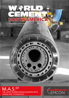
Figure 1. An aged gear reducer was a solid
piece of equipment in its day.
Figure 2. A typical motor performance curve, in
this case a Baldor-Reliance
®
#ECP4410T-4.
Figure 3. A typical Dodge
®
Torque-Arm
®
II
powertrain. There are over 2 million of these
units in service.