


 44 / 60

42
World Cement
North America 2019
Nevertheless, the most likely outcome will be a
physically larger gear reducer (or electric motor) that
absorbs more real estate than what is needed. In
this example, the motor was well oversized for the
application working horsepower requirements, and
the reducer was undersized when compared to the
nameplate horsepower.
Selecting a gear reducer
As previously explained, a replacement reducer
carries a minimum AGMA Class II mechanical
rating of 64.4 hp. (48.0 kW) at 28 RPM. In the
interest of selecting a gear reducer that will limit
lost production time, an inventoried 40:1 reduction
Dodge
®
Torque Arm II
®
, known as a shaft-mounted
reducer, was chosen (Figure 3). This style of
gear reducer uses a ductile iron, fully concentric
twin-tapered bushing system. It is offered in IP or
metric sizes, affording a qualified technician with
a transparent installation and removal from the
application shaft (Figure 4).
Shaft-mount reducers are often bore size limited. A
reducer is often oversized compared to the application
needs due to its primary selection criteria being
based on an existing head shaft diameter, in this
case 150 mm. A size 10 reducer at 28 RPM has a
mechanical rating of 122 hp. (91 kW) and a thermal
rating of 90 hp. (67 kW). Thermal ratings indicate
that the oil sump of the gear reducer will exceed
200°F (94°C), which in turn causes an exponential
breakdown of oil lubricating properties. The oil sump
heat generated when this occurs must be removed
by external means, such as a cooling fan or heat
exchanger. Thermal ratings must never be less than a
rated motor nameplate horsepower. True mechanical
ratings are a condition in which the gear reducer
will most likely fail, due to application overloads. A
60 hp. (44.8 kW) electric motor has been selected
and the thermal rating of 90 hp. (67 kW) exceeds that
horsepower. No cooling fan is needed in this scenario.
A size 10 shaft mount reducer accommodates a
150 mm twin tapered bushing. It is stocked locally
in IP and metric versions, has the needed service
factor, is highly efficient, and is equipped with the
power density required to reduce the installed real
estate needed. This reducer will be supported from
the application shaft and requires a motor mount, tie
rod kit, backstop, belt guard, and v-belt drive (or highly
efficient synchronous drive) to complete its selection.
It should be noted that, when cement plants do not
want to utilise belted drives, a very similar solution
can be selected with a NEMA or IEC flanged motor
that incorporates a direct coupler to the shaft‑mount
reducer (Figure 5).
Conclusion
Cement plants have many unique and interesting
applications. The example above specifically cites a
bucket elevator scenario in which an aged reducer
has failed. All the while, the cement plant, having
no critical application back-up plan in place, was
experiencing costly lost production time. A shift in
paradigm away from ‘read and replace as quickly as
possible and at any expense’ led to the following:
z
z
Clever reverse system engineering principles
being utilised in order to optimise the size of
replacement equipment.
z
z
Stocked, proven, and quality components
available in metric and IP being ready to be
utilised.
z
z
System efficiencies improved and long-term
operational costs reduced.
z
z
Plant production commencing quickly.
z
z
An excellent solution being successfully
implemented without issue.
When an aged reducer powering a clinker drag
conveyor, screw conveyor, bulk material handling
conveyor, or bucket elevator has reached its useful
life, the principles outlined in this article should be
given a try. The exercise will prove fruitful in getting a
cement plant back on track to profitability.
About the author
Nick Roseto is a key account manager and segment
specialist for the mining, aggregate and cement
industries for ABB Motors and Mechanical Inc. in the
US. He has a BSc in mechanical engineering from the
University of Illinois and a MSc in mechanical engineering
from Purdue University. He has been employed by ABB
for 21 years and is a professional representative of its
mechanical power transmission products, industrial
electric motors, generators, related service offerings, and
Ability
TM
digital solutions.
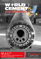
Figure 4. A Dodge
®
twin-tapered bushing
system with a full concentric attachment
mechanism.
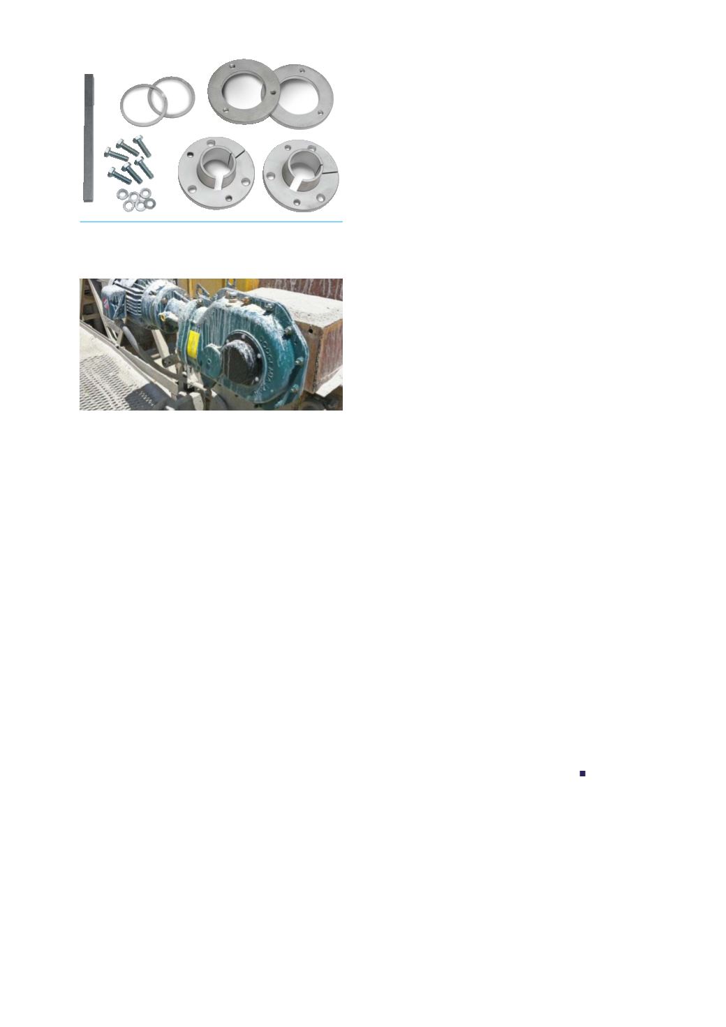
Figure 5. A typical Dodge
®
motorised
Torque‑Arm
®
II installed on a cement conveyor.