


 36 / 84

North America 2018
34 \
World Cement
Once both gear halves were installed with
chairs and drive bars, dial indicator fixtures were
assembled to facilitate the axial and radial runouts
of the girth gear. The two axial dial indicator fixtures
were attached to allow the indicators to be installed
perpendicular to the sides of the gear, 180° from each
other. The radial dial indicator fixture was attatched
so that the indicator could be installed perpendicular
to the tips of the teeth and as near to the girth
gear-pinion mesh as possible.
First, each of the plates were tack welded.
After the first plate was tacked in place, the kiln
was rotated so that the opposite plate (located
180° away) was located on top of the kiln. This
plate was then tacked in place using the same
procedure as was used with the first. Then, the
kiln was rotated 90° to spot the next plate to be
welded. This process, of rotating plates to the top
position and progressively welding them to the
shell, was continued until all of the spring plate
welds were completed. One last runout test was
completed to confirm that the gear had remained
within tolerances. After a successful runout test
(radial displacement was 0.75 mm), the chairs
and drive bars were removed from the kiln shell
and gear.
At this stage, attention was returned to the
pinion. With the girth gear fixed in place, the
adjustments needed between the gear and pinion
had to be made by moving the pinion shaft. All
of the critical measurements, such as tip, root
clearance, and backlash, were made and the pinion
shaft was adjusted to bring them into tolerance.
With that completed, a final alignment between the
gearbox and pinion shaft was made.
Conclusion
All that remained was to perform appropriate
lubrication, reinstall guarding, and perform the
required housekeeping to complete the project. With
the orientations of the pinion shaft and both girth
gear halves reversed, the system was now prepared to
drive the kiln through many more years of production
before any component would need to be replaced.
About the author
A native West Virginian and mechanical engineering
alumni of West Virginia University, Ben Sims began
his career in the cement industry as a Project Engineer
with the Essroc plant, now Argos, in Martinsburg, West
Virginia. He now supports and documents projects as a
Construction Engineer with D&L Weld Inc.
Lifting gear half.
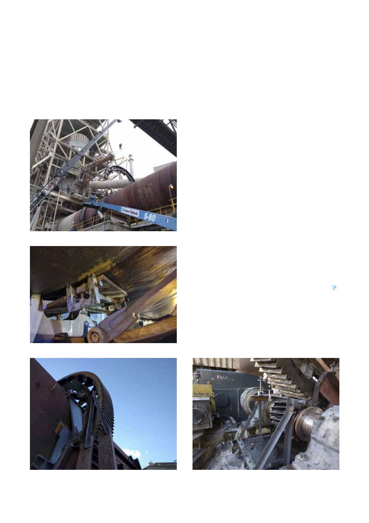
Chair and drive bar.
Axial runout fixture.
Radial runout fixture.