


 34 / 84

North America 2018
32 \
World Cement
The reasoning behind this critical decision was
straightforward. The working faces of the gear
teeth, on both the pinion and the girth gear, had
become badly worn. The steel had rolled out to the
sides of the gear and the faces of the teeth had
been deformed. With its new geometry, the teeth
of the two gears no longer meshed as they should.
The non-working face of each tooth, however, were
in excellent condition. It was now time to put the
non-working faces into service. D&L Weld Inc. of
Martinsburg, West Virginia, was tasked with this
procedure.
The project
After removing the guarding and decoupling the
gearbox, the pinion, shaft, and bearings were
removed in a single pick. In this case, the entire
assembly could be reoriented by relocating the
coupler from one end of the shaft to the other. Once
the assembly was removed, it was transported to
a local machine shop to be cleaned, deburred, and
have the coupler relocated. After it was returned,
it would simply be a matter of reinstalling the
assembly in the reversed orientation.
Next, the girth gear had to be cleaned. In any
case, this step would be a labour intensive job. In
this instance, it was especially difficult due to the
gear being lubricated using a grease, rather than
an oil bath. The crew made short work of this, using
a combination of scouring pads and solvents. Once
the gear had been scrubbed clean, grinders were
used to deburr both the sides and tops of the worn
teeth. The men operating the grinders were cautious
to avoid removing any steel beyond the burrs
themselves.
With the cleaning and deburring complete,
the pinion assembly was reinstalled in its new
orientation, with the previously non-working
gear faces now in contact with the girth gear. A
rough alignment was performed and the shaft was
re-coupled to the gearbox.
A radial runout, using dial indicators, was then
performed on the kiln shell, uphill and downhill
from the girth gear. This was done in order to ensure
that the kiln shell rotated true enough to its axis to
allow for proper gear alignment. If the runout of
the shell had proven to be excessively high, it would
have limited how well the gear could be brought
into alignment.
This particular girth gear was composed of two
halves joined to each other using four multi-jackbolt
tensioners, sometimes referred to as super bolts, at
each joint. The gear was attached to the kiln shell
with a system of spring plates. These were connected
to the gear with pins and to the kiln by welding at
tangential points around the circumference of the
shell. With one half of the gear located on top of
the kiln, rigging was installed to prepare for lifting.
The gear could then begin to be detached from the
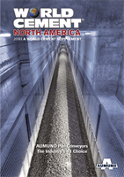
Kiln girth gear wear.
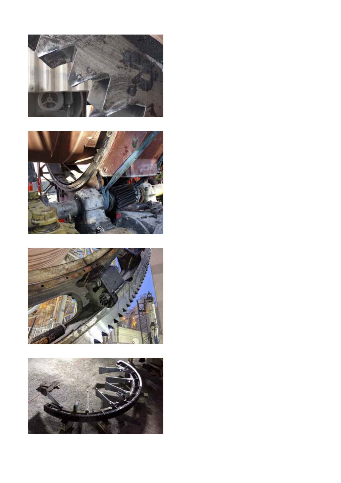
Pinion removal.
Super bolts.
Gear half with spring plates and chairs.