


 22 / 108

The Vassiliko plant has always been at
the forefront of acquiring and implementing
cutting-edge technologies; in 2014, new
alternative fuels and raw materials feeding
systems were installed. Its recent ‘green
initiative’ saw the commissioning of an 8 MWp
photovoltaic park in early 2020, making it one
of a few plants in Europe to generate its own
solar power. The Vassiliko Plant therefore,
where possible, collaborates and works with
its international technical associates in order to
stay ahead of the curve. One such initiative has
been to model its inline calciner for reducing
NO
x
, co-fired with petcoke and a combination
of alternative fuels. This article presents some
results from the calciner modelling exercise
spanning over five years.
1
The model used was
Cinar’s internally developed MI-CFD (mineral
interactive computational fluid dynamics)
model.
2,3,4
The calciner is designed to burn a variety
of fuels, including petcoke and oil, as well as
certain types of alternative fuels. Approximately
five seconds of total gas residence time is
available within the calciner, including the time
in the exit loop duct, which is sufficient to fully
combust the petcoke and oxide CO. The NO
formation/reduction in the calciner very much
depends on the mixing of the tertiary air duct
(TAD) and riser gas duct (RGD) – one of the
modelling objectives. In the present design,
a single ‘Venturi’ section was built at about
half of the calciner’s height for enhancing
the mixing of the TAD and RGD stream, as
well as for accelerating the fuel burnout and
calcinations of the meal particles.
In the calciner, combustion products from
the kiln enter the riser duct at the bottom at
a relatively higher temperature (~1200˚C).
Initially, there were two petcoke burners
located at two elevations on the east and
south sides (Figure 2), which were designed
to be multi-channel, placed in a downward
orientation with a 30° angle to the vertical.
Additionally, tertiary air was supplied to the
calciner via a duct connecting the calciner
at the lower cone-section and the bottom of
the mid-cylindrical section with a downward
orientation and a 30° angle to the vertical.
Two meal inlets were located above the conical
section of the calciner.
The plant has been designed to comply
with the EU CO and NO
x
emission limits. The
mixing ensures lower CO emissions, while the
NO
x
emissions are reduced through
kiln-generated-NO
x
destruction in the
calciner, as well as use of selective
non-catalytic reduction (SNCR).
In summary, in order to deal with
efficiency and emission targets,
the process/flow and combustion
interactions inside the kiln, calciner
and cyclones must be analysed in
detail. Generally, some of the KPIs
(kiln performance indicators) are
readily available (e.g., pressure,
temperature and exit concentrations
of gas species) but local phenomena,
like near reaction-zone information
which influences the variables of
interest (e.g., meal calcination, CO/NO
reduction/formation and fuel burnout)
are difficult to quantify and require
detailed analysis. The only practical and
economical way forward is to perform
analysis using advanced computer
models, based on mineral interactive
computational fluid dynamics (MI-CFD)
which were used at various stages of
plant improvement phases.
In most in-line calciners,
kiln-generated CO and NO
x
are
reduced more than 70%, provided that
favourable conditions of calciner fuel,
kiln combustion products and tertiary
air mixing are maintained. Through
modelling, one can identify all important
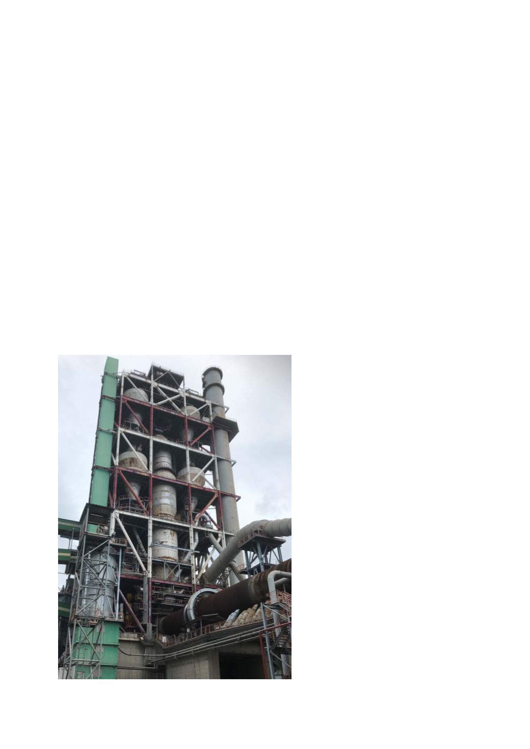
Figure 1. Vassiliko Cement Works, Cyprus.
20
World Cement
July 2020