


 26 / 108

The first and the most cost-effective approach
was to spread the fuel more within the KG and
thus increase the mixing of the fuel-released
volatiles with NO from the kiln (increasing
their destruction potential). This succeeds the
combustion of the petcoke volatiles within the
near burner region and reduces their upward
flow where more oxygen is available in the
vicinity of the tertiary air inlet. Two MI-CFD
simulations with a combination of three and
four burner combinations were carried out, and
the results showed a 38 to 51% reduction in
NO
x
and an increase of petcoke burnout from
83 to 99.3% and 99.99%, respectively. The
four-burner combination was considered to be
the optimum solution for 100% petcoke firing
conditions, as it was achieving the optimum
mixing of the fuel within the KGR.
In order to achieve the highest possible
reduction of NO from the calciner, a further
investigation took place,
necessary for when light
and pulverised AFs,
which usually have higher
nitrogen content, are fired
in higher proportions.
The investigation
was comprised of a
modification to the tertiary
air inlet in order to reduce
the downwards angle given
to tertiary air flow, and
several options of varied
angles were considered
through a refractory
wedge. The modified
geometry of a slight
upwards flow (Figure 5)
was modelled in order to
evaluate the effect of the
tertiary air’s inclined flow
on NO
x
emissions.
A comparison of the NO
emissions for progressive
modelled cases is shown in
Figure 6.
The final implemented
solution at the plant
following the above
suggestions, has been
that of four (in a symmetric
arrangement) petcoke
burners in the lower
section of the riser duct
with modified tertiary air
inlet for firing of petcoke.
Also with the new AF inlet
higher, (RDF/SRF, tyres
chips, sewage sludge,
MBM) almost 90 – 95%
of the calciner fuel can
be achieved, as well as a
further reduction in NO
x
.
The plant measured that
NO
x
emissions with AF
co-firing with petcoke
were found to vary
between 45 – 50% with a
four-burner and tertiary air
inlet modified solution.
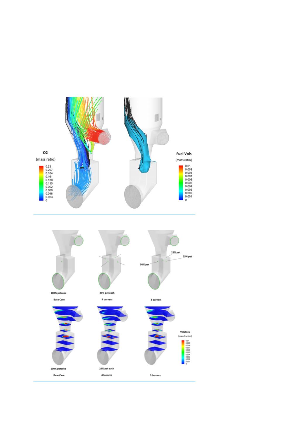
Figure 3(b). Diffusion of unreacted volatiles into the sheer layer
between the tertiary air and riser gasses.
Figure 4. (a – top) Petcoke injection from single burner (Base
Case) to 3 to 4 burners’ combination. (b – bottom) Petcoke volatile
concentrations for single, three and four burner firing combinations.
24
World Cement
July 2020