


 40 / 140

November 2018
38 \
World Cement
The projects in Table 1 are ones for which, in the
absence of detailed plant analysis, it is difficult to
identify the specific constraints preventing higher
TSR levels and the elimination of process and
emissions issues.
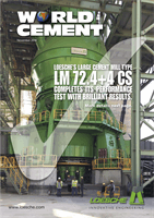
Calciner optimisation: inline calciners
In calciners, the flow biasness induced by the kiln
inlet bend must be taken into account, since it
dictates the emerging flow pattern within the
calciner riser duct. For example, in Figure 1, the
predicted results for an inline calciner fired with
heavy AF (tyre chips) are shown. At the kiln inlet
(Figure 1a), as the kiln combustion products enter
the smoke chamber, the gas flow is shifted towards
the back wall; in consequence, a lower velocity
region forms towards the front wall (kiln side). This
stratified flow persists into the narrow riser duct for
all types of calciners.
Depending on the flow angle of the tertiary air
stream(s), in inline calciners the developed
higher/lower gas velocity regions are somewhat
shifted again (Figure 1b). Oxygen from the tertiary
supply occupies most of the lower velocity front-end
region, as well as a portion of the adjacent back wall
segment, thereby slightly moving the higher-velocity
regions anticlockwise (top view). As a result, the
higher-velocity regions move from the back wall
towards the calciner sidewall: hence, heavier AF
chips may not be suspended if fired ignoring the
shift in the higher upward velocity profile.
The trajectories of the tyre chips (Figure 1c) show
that, although tyre chips were initially introduced
in the higher upward gas velocity region, their
momenta as they fall under gravity transports them
away from the higher and into the lower upward
gas velocity region. As previously shown,
1
tyre chips
confined to the lower upward gas velocity region
of the riser duct experience only about 15 – 20%
burnout before depositing on the kiln hearth
(Figure 1d). These tyre chips continue burning in
Figure 2. (a) Light fluff material, fully suspended, shown
interposed on velocity and temperature profiles; (b)
hot meal particles interposed on temperature profiles
(left: meal from only one inlet; right: meal split into two
inlets to curb the excessive temperature regions).
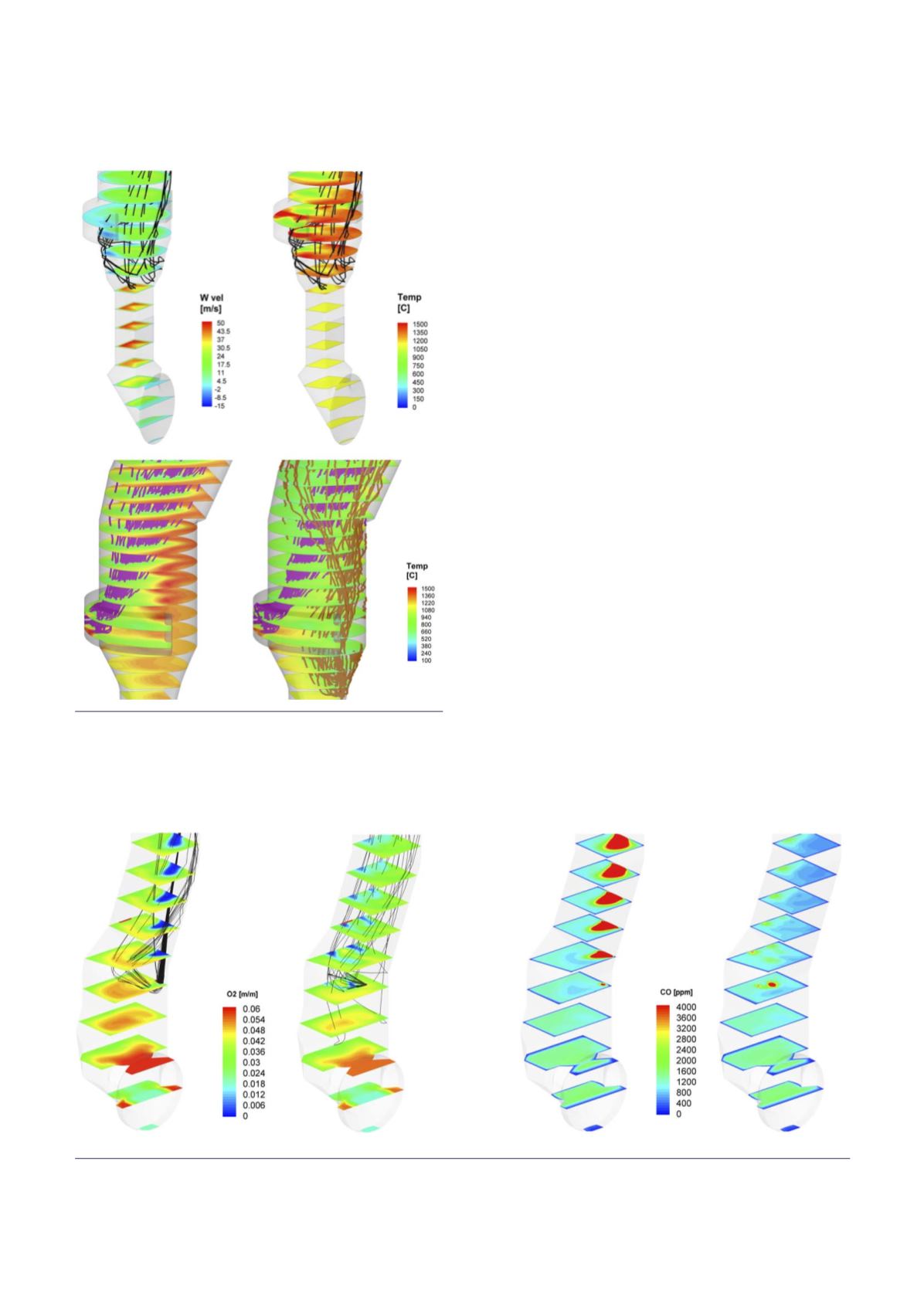
Figure 3. Results showing the cases of AF fed via screw feeder (left) and via swirl burner (right): (a) oxygen and AF
particle trajectories; (b) CO profiles (increased CO formation is removed in burner case).
(a)
(b)
(a)
(b)