


 42 / 140

November 2018
40 \
World Cement
the kiln hearth area, reaching about 70% burnout
before moving with the bed material into the kiln.
A small to moderate improvement in tyre chips
burnout can be achieved by adjusting their injection
angle, so that their trajectories are kept within
the higher upwards gas velocity regions. Further
burnout improvement can be secured through the
installation of a venturi-type refractory-bump in
the region of the chips trajectories, giving rise to
gas velocities in the range of 40 – 45 m/sec. over
a distance of 2 – 3 m. The typical venturi solution
results in a 0.5 – 1.0 mbar pressure loss, which
is offset by a higher TSR of tyre chips, as well
as a reduced need for air blasting. The latter is
minimised because the improved tyre chip burnout
within the calciner reduces the carbon in hot meal,
eliminating frequent build-ups in the calciner.
The same observations apply to lower-density
solid AF, but adjustments need to be made to the
chip trajectories to ensure that they remain in a
region of strong upward gas flow along the riser
duct length (Figure 2a). When the chip trajectories
and the required upward gas velocities combine
to ensure upward entrainment of the solid AF and
its burnout within the suspension mode, both CO
and NO emissions are not an issue. On occasion,
meal split may be required, should solid chips
disperse less into the upward gas flow and so
have the propensity to cause hot spots near the
calciner walls. These hot spots can be eliminated
by introducing meal via two meal inlets, so that an
enlarged region of moderate temperature is created
(Figure 2b).
2
When introducing lower-density AF (e.g. fluff), it
is important to design the AF inlet(s) so that
chips/particles of the material are not trapped in
lower velocity regions, in particular in recirculation
zones, as entrapped unburnt fuel volatiles increase
CO formation.
In the following example,
3
a mixed solid AF
(fine plastics, tissues, paper, and wood) was
introduced via a gravity-fed screw feeder. As the
AF injection velocities were extremely low, the AF
chips did not mix with the gas stream and ended
up in a low velocity region. In consequence, this
region became fuel-rich through the depletion of
oxygen (Figure 3a). The reducing conditions led to
CO emissions of nearly 2500 ppmv. Use of a swirl
burner allowed better dispersion of particles and
a reduction of CO to below 800 ppm (Figure 3b).
The burner momentum was designed such that the
AF chips/particles occupy the centre of the flow
without burning in the vicinity of the opposite wall,
risking damage to the calciner refractory.
Calciner optimisation: separate line
calciners
A similar AF firing strategy is also applicable to
separate line calciners (SLC), with the exception
that it is more desirable to have a higher expansion
ratio between the riser and the calciner ducts (see
the difference in expansion ratio in Figures 4a and
4b). It has been shown that this design feature
creates an external recirculation zone (ERZ) within
the calciner expanded duct section, which, due to
the evolving fuel rich conditions, assists the early
ignition of AF particles.
4
This also reduces the
NO
X
concentrations, a tendency absent in lower
expansion ratio (Figure 4b) calciner designs, which,
in specific cases, have several times higher NO
emission levels (350
–
1400 ppm).
A higher duct expansion ratio assists in burning
both higher and lower density AF in separate
line calciners, as the bigger chips are recirculated
within the lower velocity and higher velocity
regions, eventually experiencing increased burnout.
However, the propensity for high CO formation
exists if the ERZ extends further upstream and
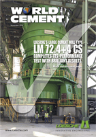
Figure 4. Two separate line calciner configurations: (a)
high expansion ratio, (b) lower expansion ratio.
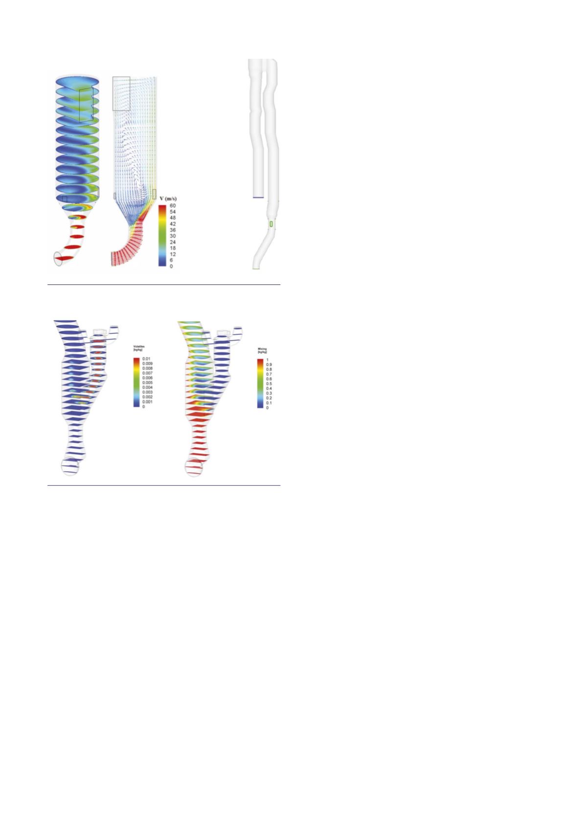
Figure 5. (a) Volatiles from the RSP and (b) mixing
profiles (red = kiln riser gases, blue = tertiary air).
Volatiles do not mix well with the kiln riser gases.
(a)
(b)
(a)
(b)