


 30 / 108

Since its market launch in 2001, this system
has been installed more than 130 times in cement
plants worldwide. Based on the experience
collected over almost 20 years of product
placement, thyssenkrupp devised and carried out
a design upgrade programme to align the cooler
to the ever-more stringent market demands for
energy efficiency and low maintenance. Several
key design aspects were targeted, in order to
maximise the performance of the cooler under
ever more taxing operating conditions.
Aeration floor design
The first improvement tackled the power
consumption of the cooler. The key feature of
the product is the separation of aeration and
clinker conveying, which allows for high cooling
performance over time, and lends a long service
life to the aeration elements. This is due to the
fact that the stationary aeration floor is covered
with a static, cold layer of clinker, which acts as
autogenous wear protection. The tracks move
above the aeration floor and convey the clinker
using a reciprocating movement.
The electrical energy consumption of the
cooler is the sum of the power consumption
of the aeration cooling fans, the hydraulic
drive powering the clinker conveying system,
and the clinker crusher. Aeration accounts for
by far the largest consumption and therefore
has the highest savings potential. The ideal
power expenditure of a fan is, if losses are to
be neglected, a function of the total pressure
increase in the fan and the volume flow delivered
by the fan.
The pressure increase is required to overcome
the three sources of flow resistance and pressure
drop in the cooler aeration:
f
The pressure drop of the aeration floor itself,
due to the flow through the narrow aeration
slits.
f
That of the static, protective clinker layer.
f
That of the active clinker bed to be cooled.
Only the fraction overcoming the flow resistance
of the active clinker bed is useful work. The
focus of the in-house research activities was on
minimising the other two components.
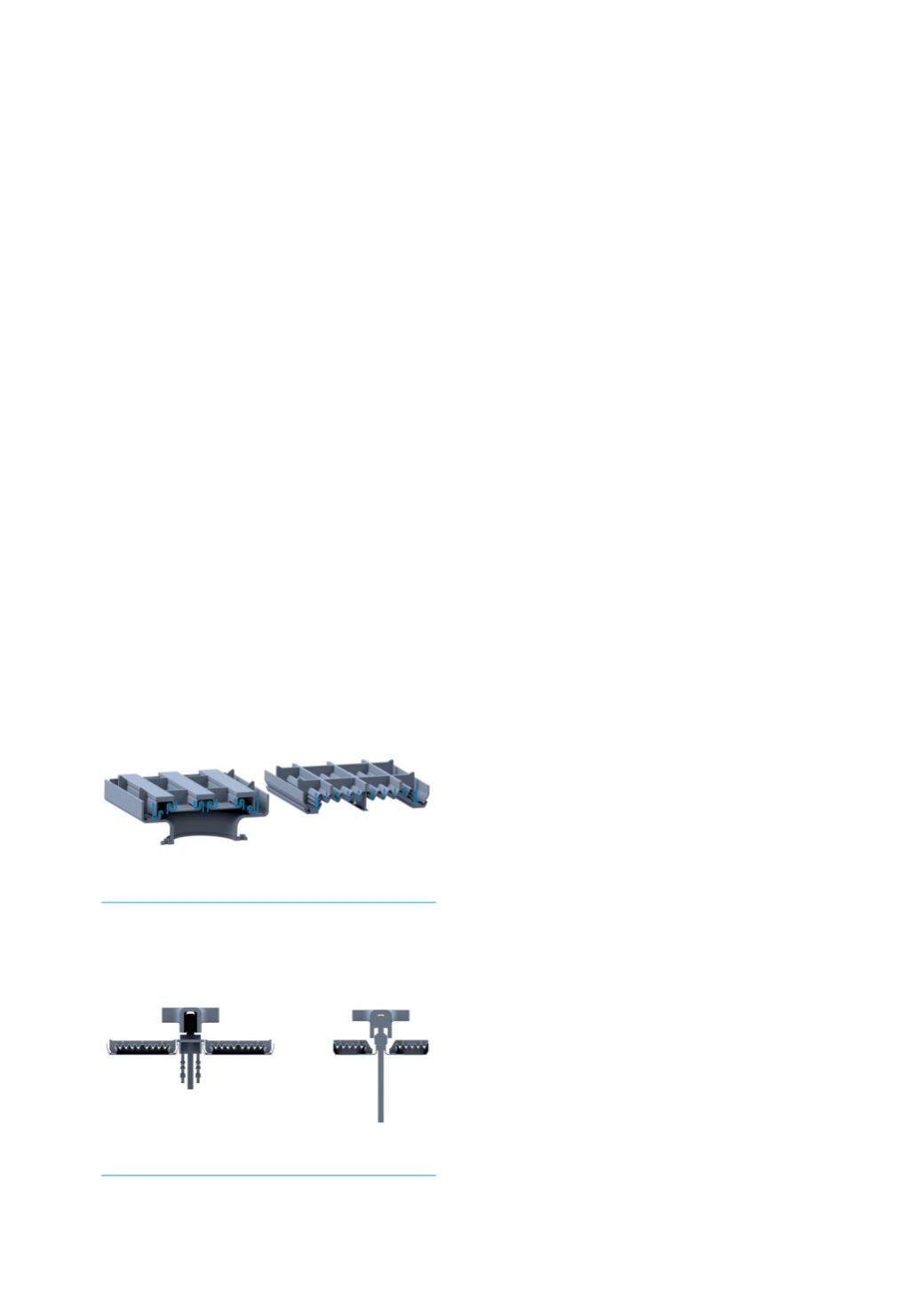
The new design of the aeration elements is a
labyrinth design, like the previous one, as shown
in Figure 1. The labyrinth-like flow path of the
cooling air prevents clinker from falling through
at the cost of a certain pressure drop. The new
element configuration reduces this pressure
drop. It increases the total air outflow area of
each unit by increasing the number of labyrinths.
This in turn reduces the air outflow velocity
through the aeration slits, effectively reducing the
pressure drop of the aeration floor.
Another benefit of the updated labyrinth
design of the aeration units is a decreased flow
resistance in the protective clinker layer on top of
the aeration floor. The previous design featured
pockets in which the clinker settled between the
aeration channels. Due to the area restriction
of the pockets, the air velocity in this area was
higher than in the rest of the static layer, resulting
in an increased pressure drop. The new design
reduces this effect, leading to additional power
savings.
In total, the improved velocity profile of the
cooling air in the aeration elements and the
static clinker layer leads to a saving of more
than 10 mbar pressure drop, which reduces
the power consumption of the fans at a given
flow of cooling air. These improved aeration
elements can also be retrofitted to older coolers.
Combined with new conveying elements with
reduced height, which decrease the overall
height of the static clinker layer, the combined
power savings of the new design can reach up to
1 kWh per t of clinker (based on measurements
carried out in several plants).
New design
The tendency in the cement industry is towards
simplified, fast, predictable maintenance of
the key equipment. Although the number of
components requiring maintenance in a polytrack
is quite small, the goal was to enhance the
ease of maintenance operations. As part of the
Figure 2. Old (left) and new (right) sealing
design.
Figure 1. Old (left) and new (right) aeration
element design with increased cooling air
outflow area.
28
World Cement
July 2020