


 32 / 108

upgrade, the entire subgrate compartment of the
cooler and the sealing were optimised. The final
result brought greater advantages than just easier
maintenance.
One target was to update the cooler sealings.
The sealings make up the juncture between the
aeration floor units and conveying elements, the
latter being connected to the hydraulic system
in the subgrate compartment. They ensure that
no clinker falls under the grate at the interface
between the static aeration floor and the moving
tracks. While the original flat guide sealings
proved to be very effective in many plants, due
to a shift towards fuels with an increased sulfur
content, the clinker size decreased significantly
in some kiln lines. In these plants, increased
maintenance, especially for the spring system,
was required to keep the sealings spillage
free. The spring system is needed to keep the
horizontal sealing aligned and tight against the
structures above the grate, and to prevent clinker
from trickling under the grate into the aeration
chambers. It requires regular maintenance,
especially in plants with very fine clinker, to
ensure spillage-free operation.
A simplified sealing, as illustrated in Figure 2,
was designed to tackle this challenge. The new
sealing arrangement was tested successfully
under challenging operating conditions. It is a
vertical, continuous sealing, without springs,
made out of hardened steel to withstand the
friction resulting from the movement of the tracks.
It has fewer components, and it is faster and
easier to install.
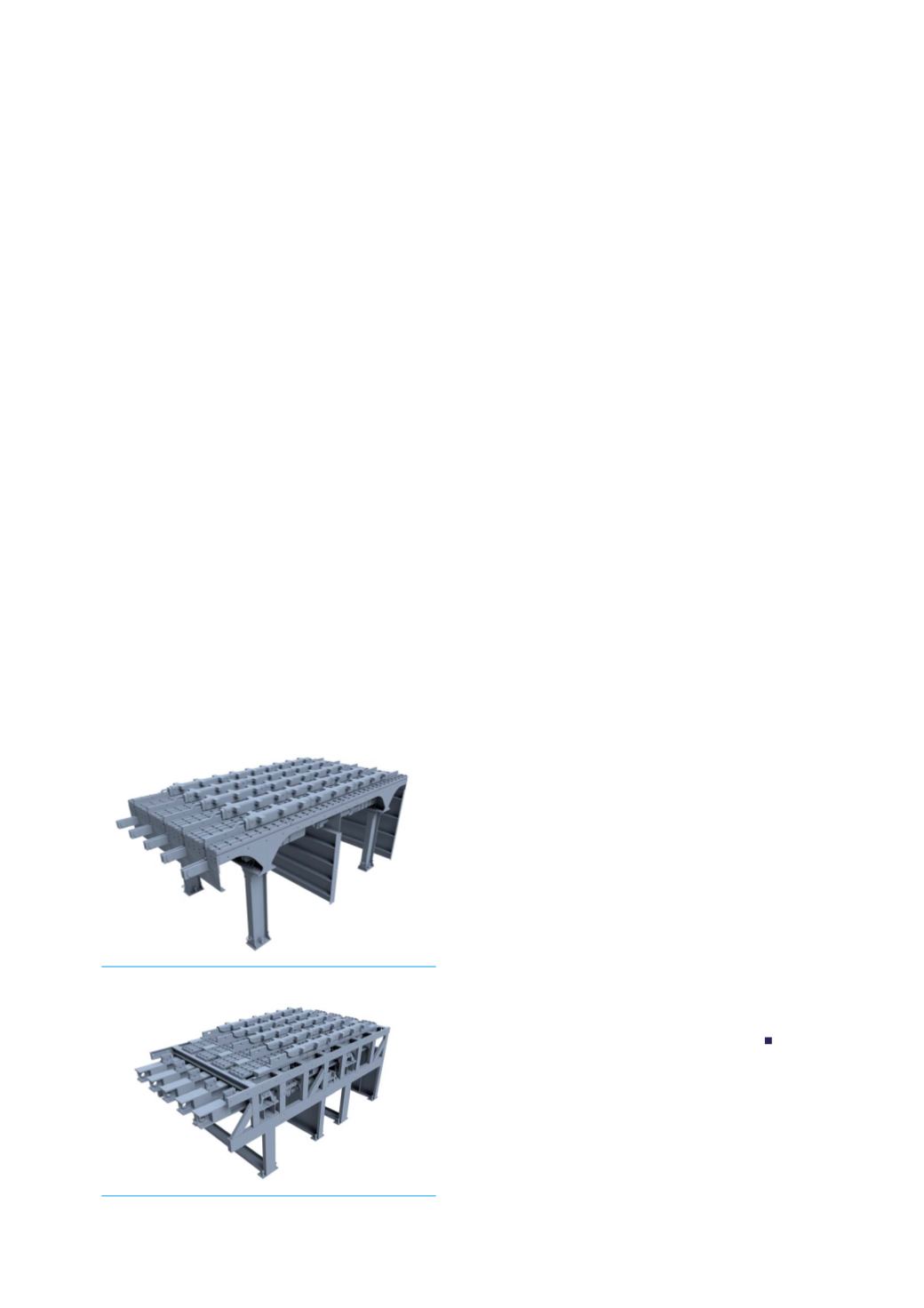
Another significant issue related to maintenance
is accessibility. For this reason, the substructure
of the grate was completely redesigned
(Figure 3) to allow unhindered access to the
bearings and hydraulic cylinders located under
the grate for inspection and maintenance. The
distribution of forces was optimised, allowing the
weight of the support structures to be reduced.
The new substructure consists of bent metal
sheets instead of profiles, which has the added
benefit of allowing faster, easier manufacturing
without machining. The reduction in weight of
the grate substructure has a positive impact on
the overall cooler cost. The investment costs for
the new product design become more attractive,
especially for conversion projects, where the
cooler modules make up the majority of the
scope of supply.
Finally, the bearing design was also altered
to improve maintainability. The entire bearing
position is lighter and is fixed to the grate
substructure with only two bolts, which makes
installation quick and easy. High quality materials
are used to manufacture the bearing components
in order to increase wear and temperature
resistance.
This new design opens up the possibility
of recirculating hot gases under the grate
of the cooler. This technology has possible
applications, for instance, for simplified emission
control. Strict NO
x
emissions limits pose
difficulties for plants with high RDF utilisation
rates, especially if a highly variable mixture
is used, leading to continuously changing
combustion conditions. This causes significant
NO
x
concentration fluctuations in both the
main gas stream and the bypass stream, which
usually reaches the stack without undergoing
NO
x
reduction, making precise control of
the NO
x
concentration at the stack more
challenging. Recirculating the bypass stream
under the cooler grate reduces the complexity of
the emissions control task.
Conclusion
The clinker cooler is a key component of any
clinker production line, and its performance
weighs heavily on the final economic performance
of a cement plant. The improvement programme
for the polytrack has resulted in optimisations in
many areas and greater customer benefit.
About the author
Valentina Bordei has five years of experience in
the cement industry, where she worked first in the
development of emission reduction technologies
and is currently a part of the pyro-processing
equipment design and technical sales team. She
holds M.Sc. titles in Environmental Engineering
and Process Engineering and Energy Technology.
Figure 3. New grate structure.
Figure 4. Old grate structure.
30
World Cement
July 2020