BMHR 2016
14 \
World Cement
Take solids flowmeters: you know what they do, how
to fix them (or who you should call to fix them), but
have you ever wondered how they work?
Do not be fooled by their apparent simplicity
– material goes in, material comes out, you get a
measurement. But what is really going on inside a
solids flowmeter? The answer will change the way you
think about this piece of equipment as you walk past it
each day.
The process
After the journey from the quarry to grinders and
the kiln, the final step in the process of making
Portland cement is the finish mill. Clinker, along with
a proportional amount of gypsum, is fed into the mill
to be ground into finished cement ready for storage
or transportation. The design of a finish mill generally
consists of a very large dia. steel tube filled with a
designated quantity of steel grinding balls. As the mill
is rotated at an optimum speed, the grinding balls
crush the clinker/gypsum mixture into a fine powder.
A high-efficiency cyclone separator controls the
particle size. The drum is generally divided into two or
three chambers with differently sized grinding media.
As the clinker particles are ground down, smaller
media are more efficient at further reducing the
particle size.
In a closed-circuit system, coarse particles are
separated from the finer product and returned to the
start of the process for further grinding. This is called
a recirculating load, and to ensure peak efficiency, the
mill should run with an optimum load.
The most common application for a solids
flowmeter here is the coarse returns downstream
from the cyclone separator. It is important that this
reading be instantaneous, since the load of the mill
needs to be maintained at a level to achieve the most
efficient grinding. With this rate feedback, the system
controller can vary the input of clinker and additive
feeds to quickly adjust for the best grinding control.
The flow rate in the coarse return process varies from
system to system, but rates of up to 800 tph (880 STPH)
are possible.
The impact of impact-based flowmeters
The most reliable solids flowmeters available are
impact based. These flowmeters have an impact plate
mounted at an angle that the material strikes as it
flows down, continuously from one point to the next.
The flowmeter sensing element – either load cells
or an LVDT-based mechanical assembly – measures
the impact force generated by the flowing material
and converts this data into an electronic signal. This
signal is converted into a mass flowrate with a very
repeatable accuracy.
The principle of an impact-based flowmeter is as
follows: when solid material is gravity fed from a chute
or pipe at a height (h), the horizontal component
of the impact force generated at the plate (F
0
) is
proportional to the mass flow rate (G) of the material.
The free body models shown in Figure 2 illustrate this
principle, and the following equations are obtained.
Figure 1. Solids flowmeters provide continuous
indication of flow rate without interrupting the
process.
Figure 2. In order to measure the material flow,
the forces and their resultant influences must be
understood.
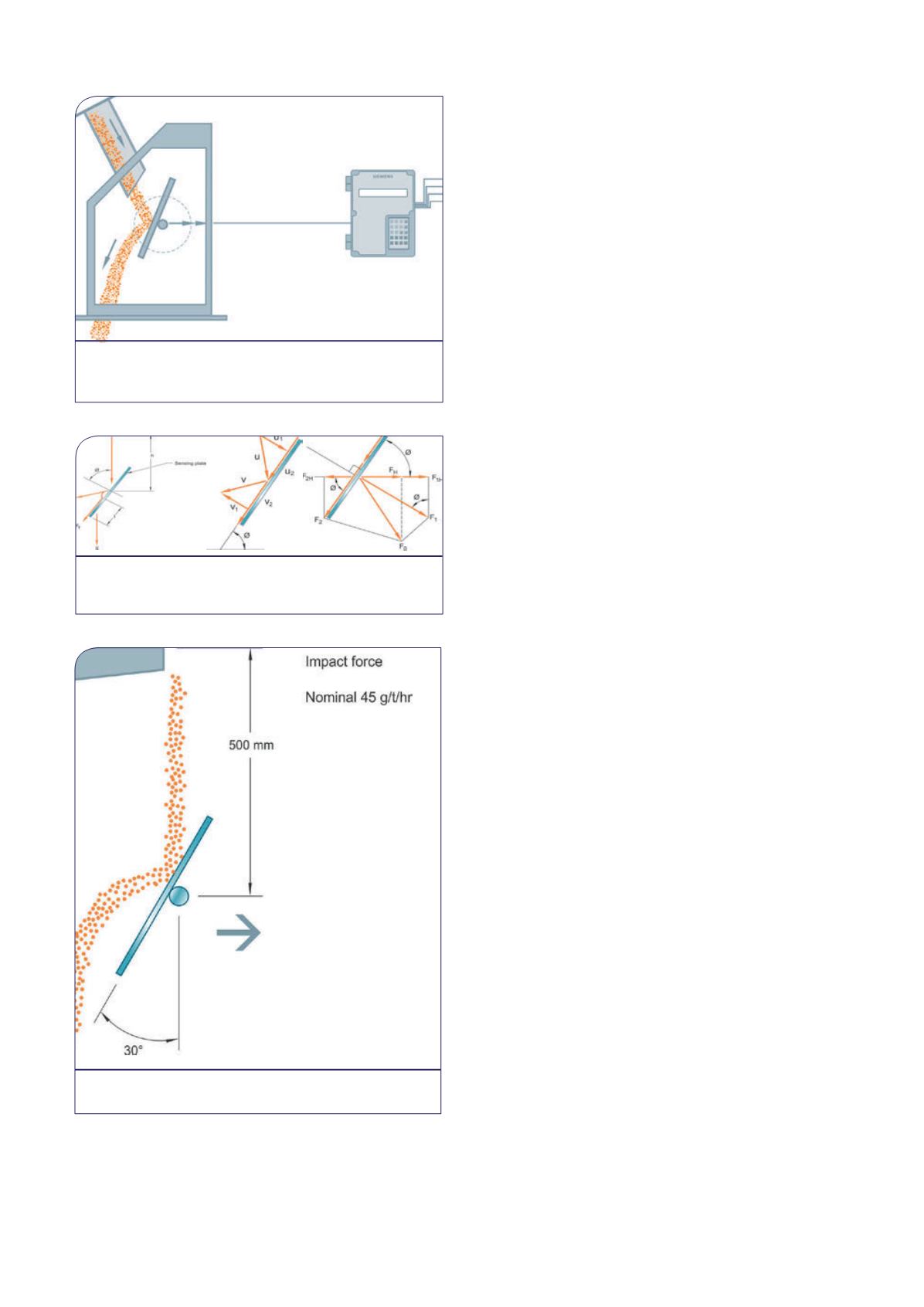
Figure 3. As a baseline for all materials a nominal
impact force is used.


