BMHR 2016
18 \
World Cement
Therefore, horizontal component F
2H
is calculated
from the following equation:
The advantage of impact technology is that the
drift due to the mechanical stability of the assembly is
eliminated. Only the horizontal force is measured, so
material buildup does not affect the output or zero
reading.
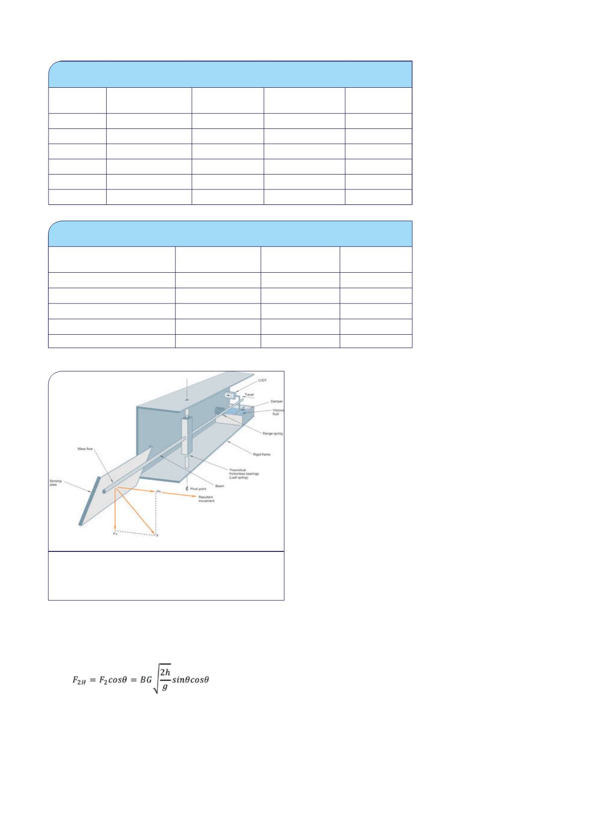
There are two ways of
implementing the solution.
One involves using an
LVDT (linear variable
differential transformer)
sensor mounted in a
frictionless pivot assembly,
shown in Figure 4.
The other option is to
use load cell technology.
Load cells offer a very
cost-effective solution for
impact-based flowmeters,
and in fact are used in a
variety of solutions such
as Coriolis and centripetal
designs as well. The
ideal load cell option
is a parallelogram style
cell, which operates in
the same way the LVDT
assembly does above in
that it does not react to
vertical forces, but only
horizontal ones due to
material impact. Material
buildup is also negated with a load cell design.
Impact force considerations
Impact force is classified in grams per tons per hour
(tph). The use of grams as a force is intentional to
equate the force component into a weight value and
is also used in calibration mass calculations. With a
steady flow of material at 1 tph, the typical impact
forces of materials are shown below:
To establish a basis for calculating flow force,
multiple materials were tested and an average or
nominal value was established for a given free fall
height and sensing plate angle. It is important to note
that if any of these variables change, the resultant
impact force will also change. This is similarly true
of the material itself: if the characteristics of the
material such as moisture content or impact absorption
changes, so too will the impact force.
The 45 g/tph force value can be compared to
placing a 45 g calibration weight on the LVDT assembly
and measuring the deflection of the plate due to this
change through the pivot and spring assemblies. The
horizontal component of the impact force on the
sensing plate is directly proportional to the flow rate
of the material over the plate. The angle at which the
material strikes the sensing plate is also very critical
for proper operation – the combined angle of the flow
guide and sensing plate should not exceed 60˚ or be
less than 50˚.
As shown in Figure 3, the horizontal force acts
against a compression spring, through a set of
frictionless bearings and is converted into a horizontal
movement (deflection). Transients are ‘smoothed’ out
Table 2: Factory calibration tests are performed to ensure the maximum accuracy
and repeatability can be acheived
Test
weight (g)
Theoretical
indication
Actual
indication
Error: % reading Error: % full
scale
0
0.000
0.000
0.000
0.000
600
0.800
0.801
0.125
0.025
1200
1.600
1.603
0.185
0.075
1800
2.400
2.405
0.208
0.125
2400
3.200
3.204
0.125
0.100
3600
4.000
4.000
0.000
0.000
Table 3: When installed correctly solids flowmeters can be accurate and
repeatable measurement devices
Actual flow
Indicated flow Error: %
reading
Error: % full
scale
0.00
0.00
0.00
0.00
4.00
4.03
0.75
0.15
8.00
8.07
0.875
0.35
12.00
12.10
0.833
0.50
16.00
16.05
0.312
0.125
Figure 4. The impact forces on the sensing plate
are just part of the equation for reliable flow
measurement, the whole assembly must be designed
for an accurate solution.


